Skiply Smilio Action Multiservices – Assembly, Activation & Configuration
After we recently introduced you to the Skiply Smilio Action Multiservices in more detail, including possible use cases that can be implemented, we wi…


– 📖🕓 ≈ 6 min – Article last updated: 01/31/2022 After I get you in Part 1 and Part 2 of this series of posts showed what you can do about…
– 📖🕓 ≈ 7 min – Last modified on 11th April, 2024 Last week, in Part 1 of this small series, I showed you which components you can basically use to…
– 📖🕓 ≈ 9 min – Last modified on 11th April, 2024 As recently announced, I would like to use the example of two LoRaWAN® sensors and the B.One Gallery visualization…
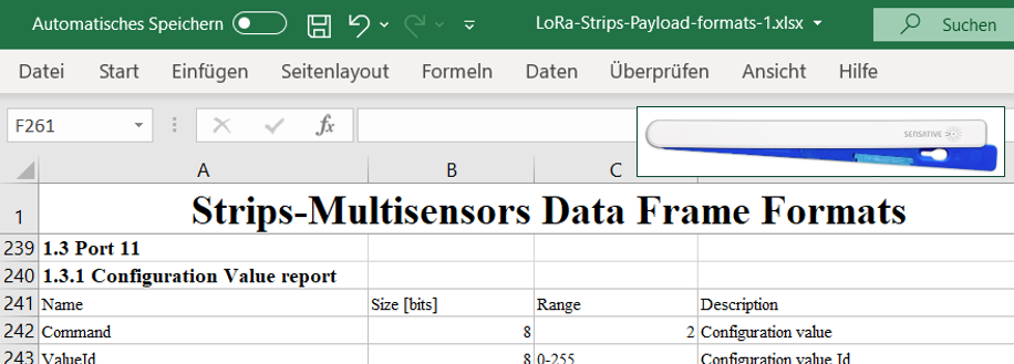
– 📖🕓 ≈ 4 min – Last modified on 16th April, 2024 In Michael ‘s last posts, he has already shown how a payload is composed using the Sensative Strips sensors…
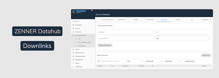
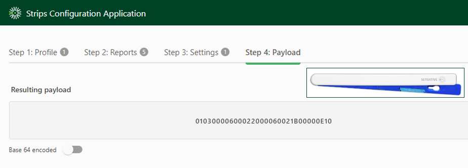
– 📖🕓 ≈ 6 min – Last modified on 11th April, 2024 I recently showed you how you can easily configure your strips (LoRaWAN) sensors yourself using the “Strips Configuration Application”.…
– 📖🕓 ≈ 5 min – Last modified on 11th April, 2024 Like me, you are using one of the Sensative Strips sensors for LoRaWAN and are wondering how you can…